

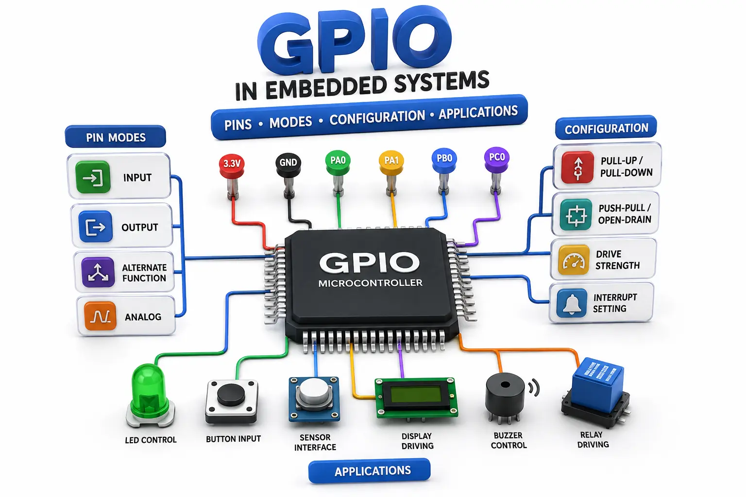
GPIO in Embedded Systems Complete Guide to Pins Modes Configuration and Applications
Navigate through this article using the table of contents below
Table of Contents
No headings found in this article.
A single microcontroller pin can read a button, control an LED, trigger an interrupt, communicate with a peripheral, or even influence a motor-control circuit. The challenge is not knowing that GPIO exists—it is understanding how to configure each pin correctly and safely.
GPIO looks simple at first: configure a pin as input or output and read or write a logic level. In real embedded products, however, pin multiplexing, pull resistors, drive strength, electrical limits, interrupts, and alternate functions determine whether the design works reliably.
What Is GPIO and Why Is It Important?
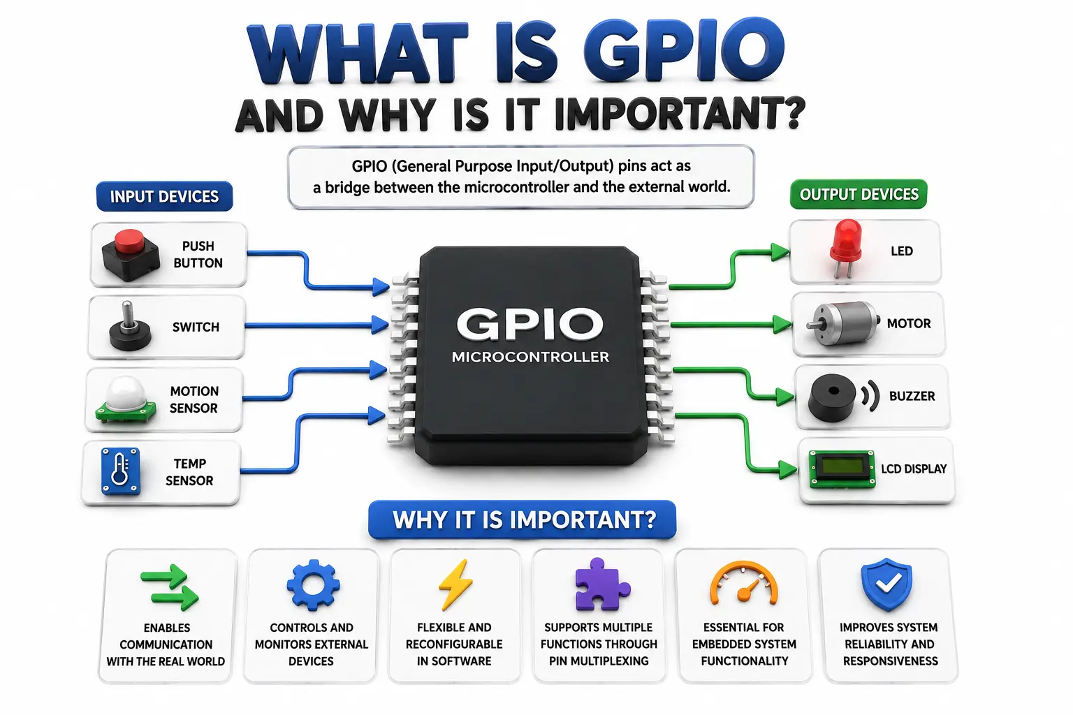
General-purpose input/output provides a programmable digital interface between a microcontroller and external hardware. An input pin allows firmware to observe an external logic level, while an output pin allows firmware to control a connected circuit.
A GPIO pin can typically be used for functions such as:
Reading push buttons and switches
Driving LEDs and indicators
Monitoring digital sensors
Controlling enable, reset, or power signals
Generating chip-select signals
Detecting external events through interrupts
The important point is that GPIO is not simply a physical metal connection. A modern microcontroller pad contains configurable circuitry that determines how the external signal is electrically handled. Depending on the device, configuration may include direction, pull resistors, output type, drive strength, slew rate, input filtering, and alternate-function selection.
This is why GPIO configuration must always be based on the specific microcontroller's datasheet and reference manual rather than assuming every device behaves identically.
Understanding GPIO Pin Modes
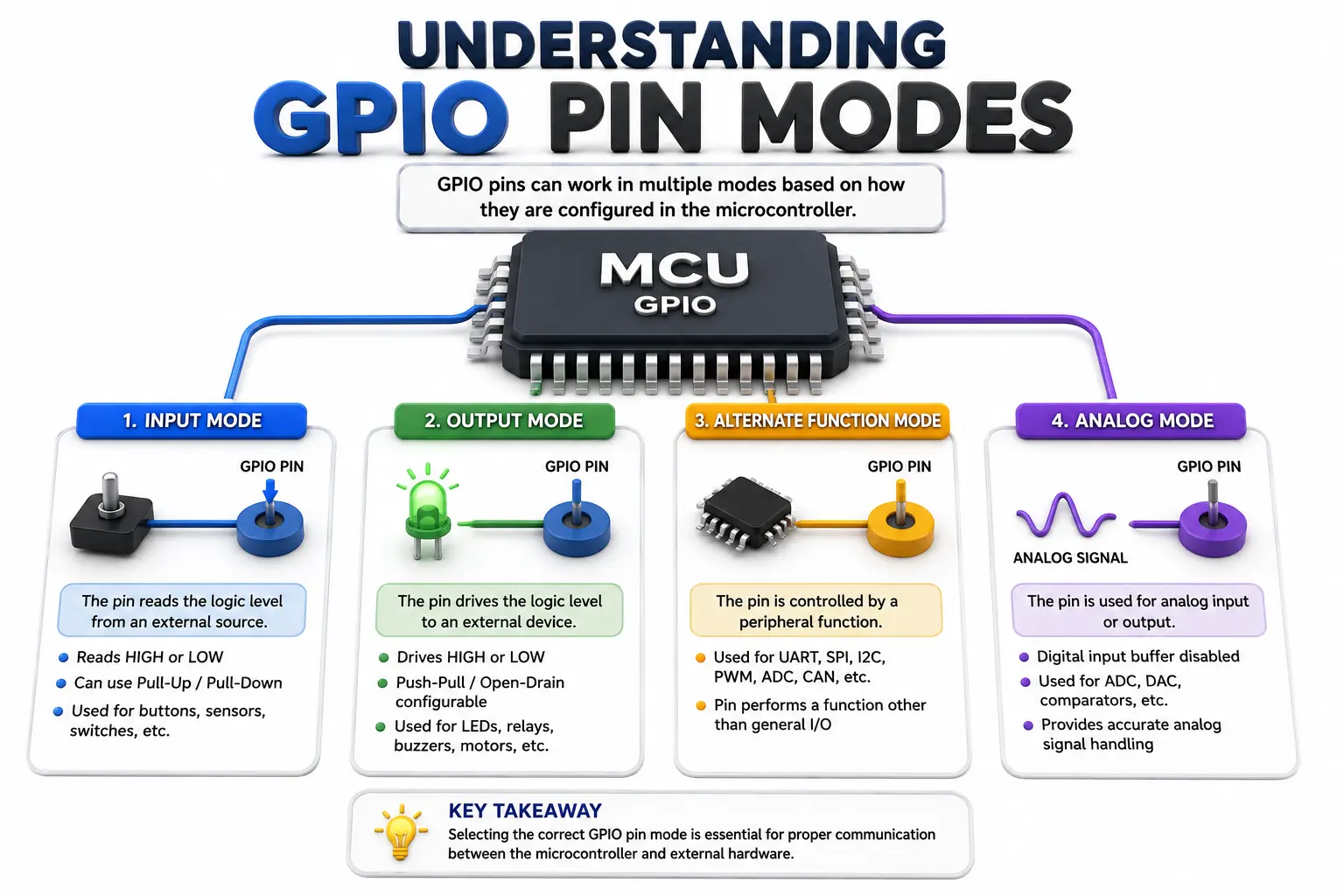
The most fundamental configuration is choosing how the pin interacts with the external circuit. The exact names vary between microcontrollers, but common modes include digital input, digital output, alternate function, and analog mode.
Digital input: The pin receives an external logic signal. The input circuitry interprets the voltage as HIGH or LOW according to the device's electrical thresholds.
Digital output: Firmware controls the pin's logic state. Depending on the output architecture, the pin may actively drive HIGH and LOW or only actively pull in one direction.
Alternate function: The physical pin is assigned to another peripheral such as UART, SPI, I²C, PWM, timer capture, or another hardware block. Pin multiplexing determines which peripheral signal reaches the pad.
Analog mode: The digital input/output circuitry is typically disabled or altered so the pin can be used by ADC, DAC, comparator, or other analog circuitry.
When configuring a pin, engineers should verify:
Direction and operating mode
Pull-up or pull-down requirement
Output type
Voltage compatibility
Maximum source/sink current
Alternate-function mapping
Startup or reset state
Understanding these options prevents configuration errors that can otherwise appear as software bugs.
Pull-Up, Pull-Down, Push-Pull, and Open-Drain
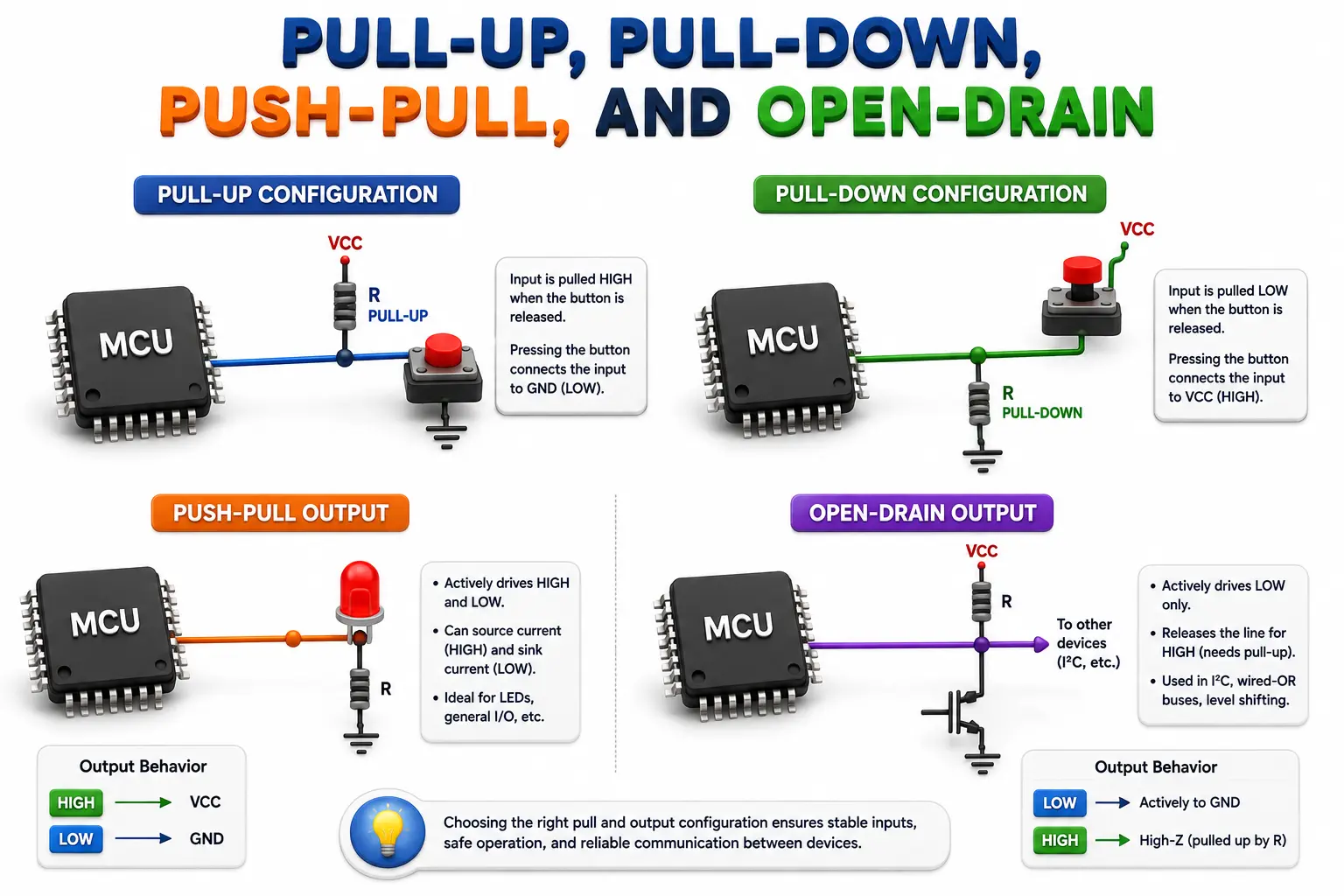
An input pin normally has high impedance, meaning it does not strongly drive the signal toward HIGH or LOW. If nothing externally determines its voltage, the input can float and produce unpredictable readings.
A pull-up connects the signal weakly toward the supply voltage, while a pull-down connects it weakly toward ground. Internal resistors are convenient, but their resistance and electrical characteristics vary between microcontrollers.
For example, a button can be connected so that:
A pull-up keeps the input HIGH when the button is released.
Pressing the button connects the input to ground.
Firmware interprets LOW as the pressed state.
Output configuration is equally important. Push-pull outputs actively drive both logic states, making them suitable for many digital control signals. Open-drain outputs actively pull the line LOW but release it for HIGH, normally requiring a pull-up.
Open-drain operation is particularly useful for shared signaling and interfaces such as I²C. It also prevents two devices from aggressively driving opposite logic levels on the same line.
For reliable designs, do not select pull resistors or output modes merely because they are available in the configuration API. Consider the external circuit, required rise/fall time, leakage current, voltage levels, and bus behavior.
How to Configure a GPIO Pin Correctly
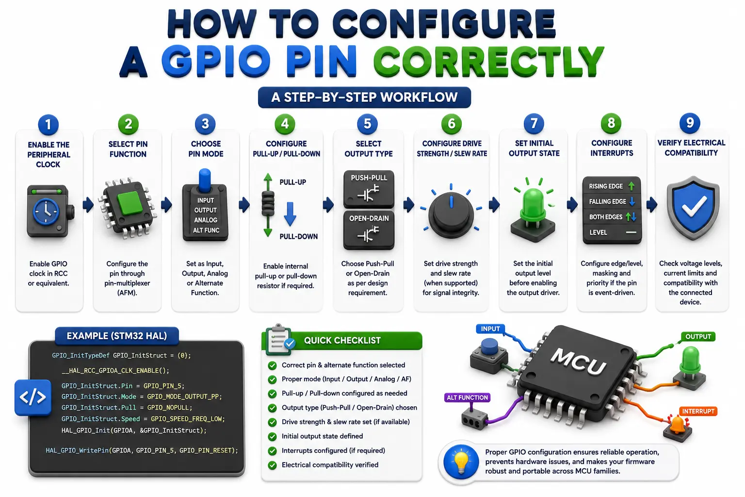
GPIO configuration normally follows a predictable sequence, although register names and implementation details differ across MCU families. A robust initialization process starts by identifying the exact pin and its electrical requirements.
A typical workflow is:
Enable the peripheral clock if the MCU requires GPIO clock gating.
Select the pin's function through the pin-multiplexer configuration.
Choose input, output, analog, or alternate-function mode.
Configure pull-up or pull-down settings where required.
Select output type, such as push-pull or open-drain.
Configure drive strength or slew rate when supported and necessary.
Set the initial output state before enabling the output driver when the application requires a controlled startup condition.
Configure interrupts if the pin is event-driven.
Verify electrical compatibility with the connected device.
For GPIO in Embedded Systems, this initialization discipline is more important than memorizing individual register names because different MCU families use different GPIO architectures.
Firmware should also avoid unnecessary read-modify-write operations on shared GPIO registers when atomic set/clear mechanisms are available. This is particularly important when interrupts or multiple execution contexts can modify the same port.
GPIO Polling, Interrupts, and Practical Applications
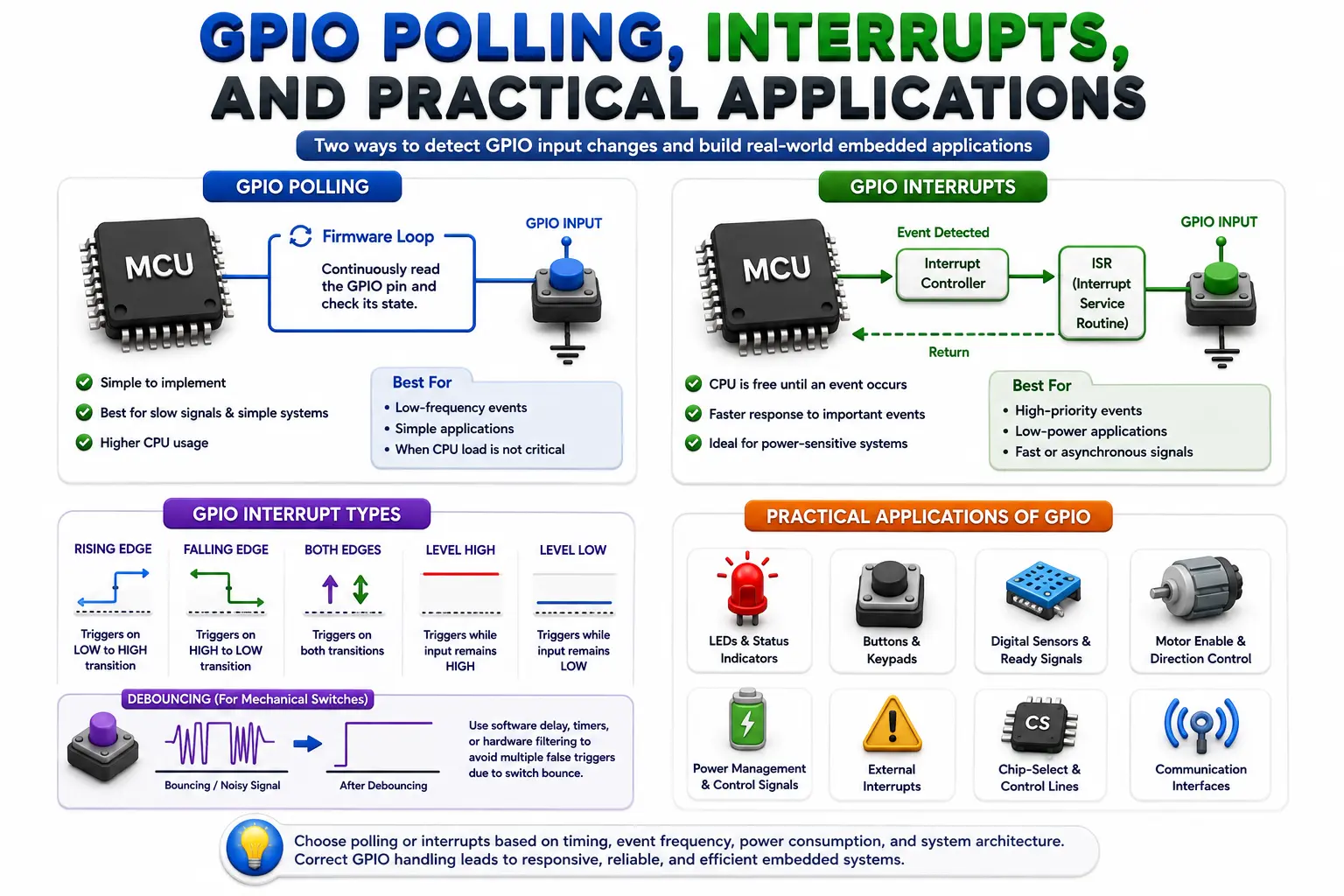
There are two common software approaches for detecting GPIO input changes: polling and interrupts.
With polling, firmware repeatedly reads the input and checks whether its state has changed. It is straightforward and can work well for slow signals, simple applications, and systems where CPU overhead is acceptable.
With interrupt-driven GPIO, hardware detects a configured edge or level and notifies the processor. This allows firmware to respond to events without continuously checking the pin.
Interrupt configuration may involve:
Rising-edge detection
Falling-edge detection
Both-edge detection
Level-sensitive detection
Interrupt masking
Priority configuration
Debouncing for mechanical switches
A mechanical button is a classic example. Pressing or releasing it can generate several rapid transitions because of contact bounce. Software debouncing, hardware filtering, or a combination of both can prevent these transitions from being interpreted as multiple legitimate events.
GPIO is widely used for:
LEDs and status indicators
Buttons and keypads
Sensor-ready signals
Motor-enable controls
Reset and power-management signals
External interrupts
Chip-select and control lines
Choosing polling or interrupts should depend on timing requirements, power consumption, event frequency, and system architecture rather than habit.
GPIO Design Mistakes and Best Practices
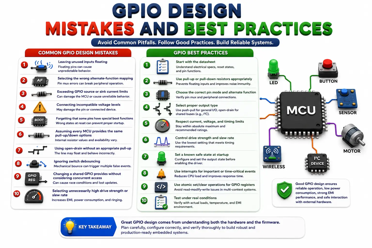
Many GPIO problems originate from configuration assumptions rather than complex firmware. A pin may appear to work during testing but fail under different electrical conditions, startup states, temperatures, or connected loads.
Common mistakes include:
Leaving unused inputs floating
Selecting the wrong alternate-function mapping
Exceeding GPIO source or sink current limits
Connecting incompatible voltage levels
Forgetting that some pins have special boot functions
Assuming every MCU provides the same pull-up/down options
Using open-drain without an appropriate pull-up
Ignoring switch debouncing
Changing a shared GPIO register without considering concurrent access
Selecting unnecessarily high drive strength or slew rate
Good GPIO design begins with the electrical specification and ends with firmware verification. Check the datasheet for input thresholds, absolute maximum ratings, recommended operating conditions, leakage, drive capability, and reset states.
For production systems, also consider electromagnetic compatibility. Fast GPIO transitions can increase signal integrity problems and electromagnetic emissions. Where the MCU supports configurable slew rate or drive strength, use the lowest setting that satisfies timing requirements.
Building Practical GPIO Skills
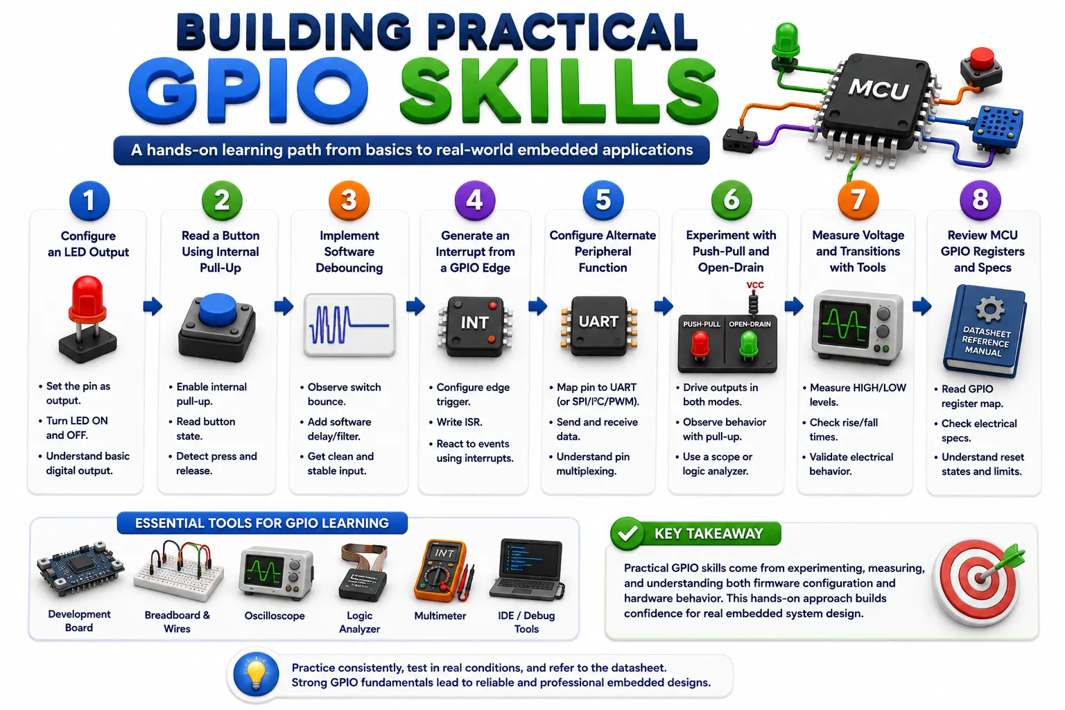
Learning GPIO effectively requires more than writing a program that switches an LED. A stronger learning sequence is:
Configure an LED output.
Read a button using an internal pull-up.
Implement software debouncing.
Generate an interrupt from a GPIO edge.
Configure an alternate peripheral function.
Experiment with push-pull and open-drain behavior.
Measure voltage and transitions with laboratory equipment.
Review the MCU's GPIO registers and electrical specifications.
This progression connects firmware configuration with actual hardware behavior and prepares learners for more complex embedded interfaces.
Conclusion
GPIO is one of the first embedded concepts engineers encounter, but it remains important throughout professional development. The same fundamental pin interface can participate in simple LED control or become part of a sophisticated peripheral, interrupt, power-management, or communication architecture.
The key is to understand GPIO as both a software configuration problem and an electrical interface problem. Correct direction, pin multiplexing, pull configuration, output type, timing, current capability, and interrupt behavior all contribute to reliable operation.
For learners using JastTech, practical GPIO exercises can provide a strong foundation for progressing toward microcontrollers, Embedded C, RTOS development, communication protocols, and complete embedded product development. Engineers who understand why a GPIO configuration works—not just which API function to call—are better prepared to debug real hardware and build reliable embedded systems.